PIN GRID ARRAY SOCKETS
SOLDER TAIL / SURFACE MOUNT
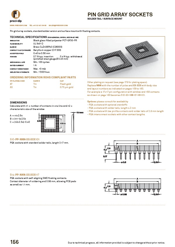
Pin grid array sockets, standard solder version and surface mount with floating contacts.
TECHNICAL SPECIFICATIONS (FOR GENERAL SPECS, SEE PAGE 155)
INSULATOR Black glass filled polyester PCT-GF30-FR
FLAMMABILITY UL 94V-O
SLEEVE Brass CuZn36Pb3 (C36000)
CONTACT CLIP (6 FINGER) Beryllium copper (C17200)
ACCEPTED PIN Ø 0.40 to 0.56 mm
FORCES 0.7 N typ. insertion 0.4 N typ. withdrawal
(polished steel gauge Ø 0.46 mm)
MECHANICAL LIFE Min. 100 cycles
RATED CURRENT 1 A
CONTACT RESISTANCE Max. 10 m��
DIELECTRIC STRENGTH Min. 1’000 VRMS
ORDERING INFORMATION ROHS COMPLIANT PARTS
PP PLATING CODE SLEEVE CLIP
87 Tin Flash gold
83 Tin 0.75 μm gold
DIMENSIONS
Calculate with n1 = number of contacts in one line and n2 =
characteristic size of the window
A = n1x2.54
B = (n1-1)x2.54
C = (n2x2.54)-0.40
510-PP-NNN-XX-XXX101
PGA sockets with standard solder tails, length 3.17 mm.
514-PP-NNN-XX-XXX117
PGA sockets with self-aligning SMD floating contacts.
Contact diameter of soldering end 0.98 mm, allowing PCB pads
as small as 1.1 mm.
156
Other plating on request (see page 178 for plating specs).
Replace NNN with the number of poles and XX-XXX with body size
and layout numbers as indicated on pages 159 to 160.
For example a 17x17 pin configuration with window and 168 contacts
as shown on page 160 becomes 510-83-168-17-101101.
Options: please consult for availability
- PGA sockets with optional standoffs
- PGA sockets with solder tails, length 4.2 mm
- PGA sockets with low profile contacts and solder tails of 2.8 mm length
- PGA interconnect sockets with other contact lengths.
WWW.PRECIDIP.COM TEL +41 32 421 04 00 SALES@PRECIDIP.COM
Due to technical progress, all information provided is subject to change without prior notice.