

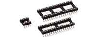


The values listed below are general specs applying for PRECI-DIP DIL sockets. Please see individual catalog page for additional and product specific technical data.
Operating temperature range: -55 ... +125 °C
Climatic category (IEC): 55/125/21
Operating humidity range: annual mean 75 %
Max working voltage: 100 VRMS/150 VDC
PRECI-DIP sockets are recognized by Underwriters Laboratories Inc. and listed under "Connectors for Use in Data, Signal, Control and Power Applications", File Nr. E174442.
Mechanical characteristics
Clip retention Min. 40 N (no displacement under axial force applied)
Contact (sleeve / clip) retention Min. 3.3 N acc. to MIL-DTL-83734, pt 4.6.4.2
Electrical characteristics
Insulation resistanace at 500 V AC between any two adjacent contacts Min. 10'000 MΩ
Capacitance between any tow adjacent contacts Max. 1 pF
Air and creepage distances between any two adjacent contacts Min. 0.6 mm
(Min. 0.2 mm FOR SHRINK-DIP SOCKETS)
Environmental characteristics
The sockets withstand the following environmental tests without mechanical and electrical defects:
- Dry heat steady state IEC 60512-11-9.11i / 60068-2-2.Bb: 125 °C, 16h
- Damp heat cyclic IEC 60512-11-12.11m / 60068-2-30.Db: 25/55 °C, 90 – 100 %rH, 1 cycle of 24 h
- Cold steady state IEC 60512-11-10.11j / 60068-2-1.A: -55 °C, 2 h
- Thermal shock IEC 60512-11-4.11d / 60068-2-14.Na: -55/125 °C, 5 cycles 30 min
- Sinusoidal vibrations IEC 60512-6-4.6d / 60068-2-6.Fc: 10 to 500 Hz, 10 g, 1 octave/min, 10 cycles for each axis
- Shock IEC 60512-6-3.6c / 60068-2-27.Ea: 50 g, 11 ms, 3 shocks in three axis
During the above two tests no contact interruption >50 ns does appear.
- Solderability J-STD-002A, Test A, 245°C, 5 s solder alloy SnAg3.8Cu0.7
- Resistance to soldering heat J-STD-0020C, 260°C, 20 s
- Resistance to corrosion:
Salt spray test IEC 60068-2-11.Ka: 48 h
Sulfur dioxide (SO2) test IEC 60068-2-42 Kc: 96 h at 25 ppm SO2, 25 °C, 75 %rH
Hydrogen sulfide (H2S) test IEC 60068-2-43 Kd: 96 h at 12 ppm H2S, 25 °C, 75 %rH
Solderless compliant Press-Fit characteristics
Press-fit characteristics measured acc. to IEC 60352-5
Press-in force: 90 N max. (at min. hole dia.) / 65 N typ.
Push-out force: 30 N min. (at max. hole dia.) / 50 N typ.
Push-out 3rd cycle: 20 N min. (at max. hole dia.)
PCB Hole Dimensions
2.54 mm grid Finished hole Ø: 1 + 0.09/-0.06 mm
Drilled hole Ø: 1.15 ± 0.025 mm
PCB Hole Plating
PCB surface finish Hole plating
Tin 5-15 µm tin over min. 25 µm copper
Copper min. 25 µm copper
Gold over nickel 0.05-0.2 µm gold over 2.5-5 µm nickel
over min. 25 µm copper
packaging
- Standard connector packaging is card box.

- SMD mount connectors available on request with Tape & Reel packaging acc. to EIA Standard 481. These products are marked with the symbol